Developing with ARM Microcontrollers/Processors - Connect the ST-Link v2 Interface to the STM32 Microcontroller - Part 1
Previous Page: Introduction to the CoIDE
At this point, the IDE (Integrated Development Environment) software has been installed.
The interface software that connects to the USB port called the ST-link has also been
installed. If you don’t have the software installed, follow the links to these videos or
go to newbiehack.com for more information.
For the circuits in these videos, I’ll be using a setup like this, which is the
microcontroller soldered onto a breakout.
The breakout is connected to three breadboards
which provide access to all of the pins and also provides two tie-strips for each pin in
line. You can get this prototyping setup here. In this video we’re going to
setup the breadboards and add the components necessary to transfer programs from the IDE,
from the computer, to this microcontroller using the ST-Link. The first thing we’ll do is tie
all of the power rails from each breadboard together, so we have power (positive which is the VCC) and negative
which is ground, so we can provide power to the microcontroller, connecting
the power to the appropriate pins.
To do this, we will connect the positive and negative from
each breadboard tie strips to the next one so the positive will go to the positive on each breadboard, the
negative will go to the negative on each breadboard, so let’s get started. We’ll take
the first wire, go from the negative to the negative on the other side, and then from the
positive here to the positive.
This side is complete, now we’ll do the other side connecting
these two power rails together. We’ll start with the negative which is ground, to the negative
on the other power rail, and then from the positive back to the positive. You want to make
sure that the two wires are not touching. I’m going to move these apart a little bit just in
case.
Now we need to find out which of these pins need to connect to ground and VCC. To do this,
we’re going to use an STM32 F030 cheat sheet that describes what
each pin does on this breakout board. You’ll find the first video explaining the ARM development
and scroll down and you’ll see the
diagram. Use the scroll bars to be able to see the entire diagram. On the left of the diagram
you’ll find pins 1 through 30, then 31, 32, 33, 34 on the bottom. On the right, you’ll find
the remaining pins, 35 through 64. So let’s see which pins are associated with power so we can power
the microcontroller. Already we can see that the #1 pin is associated with power the VDD Digital
Power Supply, so let’s go ahead and connect that one. As on the diagram, the #1 pin is located
at the corner of the breakout board.
We’ll first bridge these two tie strips together; that’s
associated with the #1 pin.

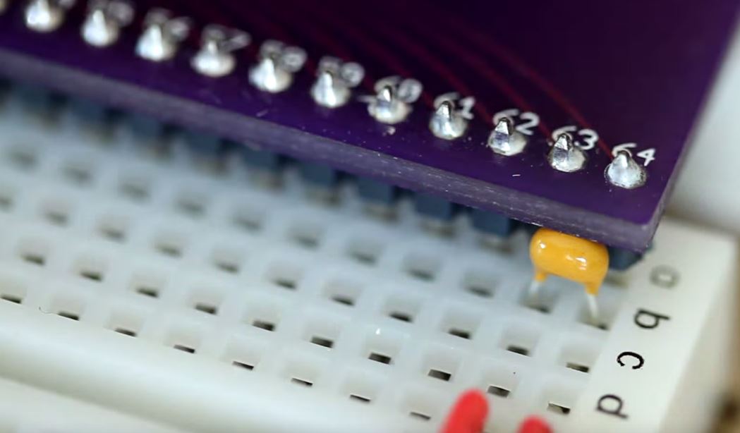
Now we want to take the #1 pin this tie strip and put it to the
plus. For good measure I’m going to add a bypass capacitor which is a .1 microfarad capacitor.
In general I’ll put this next to all of the power and ground connections and generally I’ll
put them as close to the chip as possible but in this case there is only a single VDD and there
is no ground next to it so I’m putting it at the closest place I can to the ground and the power.
On theSTM32 F030 cheat sheet, we can see that there are ground and
power supply pins at 12 and 13 but these are VSSA which is ground and VDDA which is power, but
for the analog to digital converter. We’re not going to be connecting anything to these pins at
this time since we’re not going to be using the analog to digital converter. Scrolling down, we
do notice that pin 31 is VSS which is ground, and pin 32 which is the same as pin 1. We’re going
to go ahead and plug both of these into the power rails, the ground into the minus and the VDD
supply into the plus. Just like on pin 31 we’re going to extend the tie strips by connecting them
together (31 and 32).
Take the 31 pin and connect it to minus rail and pin 32
goes to the plus rail.
Again we’ll use the bypass capacitor which is .01 uf and we’ll put it
between the power and ground pins as close to the board as possible. The capacitor is spanning
between pins number 31 and 32.
Let’s check the other side of the board to see if there are any
more. We have 63 and 64, ground and positive supply so let’s go ahead and connect those. We’ll
do the same thing with the tie strips.

63 is ground so we’ll take that one to the ground rail
or negative rail. 64 is positive so take that one to the plus rail.
Add another capacitor between pins 63 and 64.
Now we need to connect the
ST-Link v2 to the microcontroller.
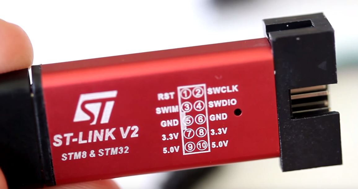
This will give us the ability to
transfer programs to the microcontroller using this as an interface between the computer and
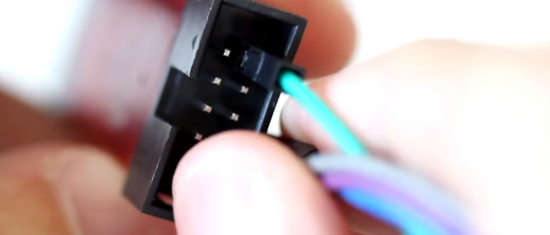
the microcontroller. The ST-Link comes with a cable that has four female headers on each end
that will connect to four pins on the back of the ST-Link.
The pins we’re going to be using as
the SWCLK, SWDIO, the SWCLK is the clock and the SWDIO is the data, input/output. We’ll be using
the ground (GND) and the 3.3v. You also have a 5v connection if you need it, it gives you the
option to use 5v on you board. You’ll notice there is a notch which corresponds to the
notch that is on the left hand side of the diagram on the ST-Link. We’ll be using the ones on the
other side and the pins that we’ll be using will be the ones on the top right looking from this
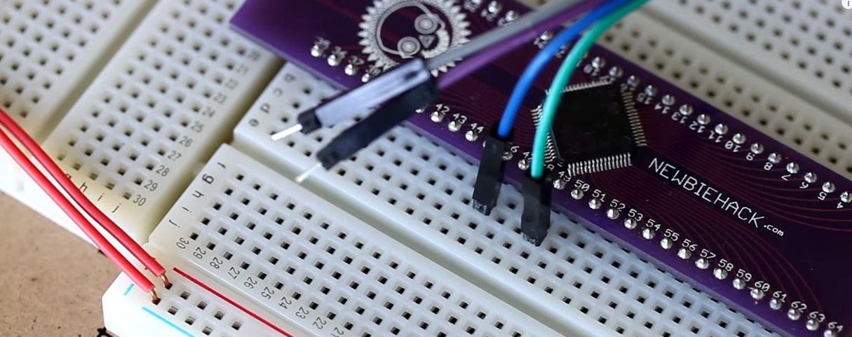
direction. The first that we’ll connect is the SWCLK which is the clock and we’ll use the green
wire for that.
So we have the green wire connected to the first pin and now we’ll go in order
so we’ll use the blue for the SWDIO.
The ground pin is next, which is the next wire in the ribbon
cable, which is purple.
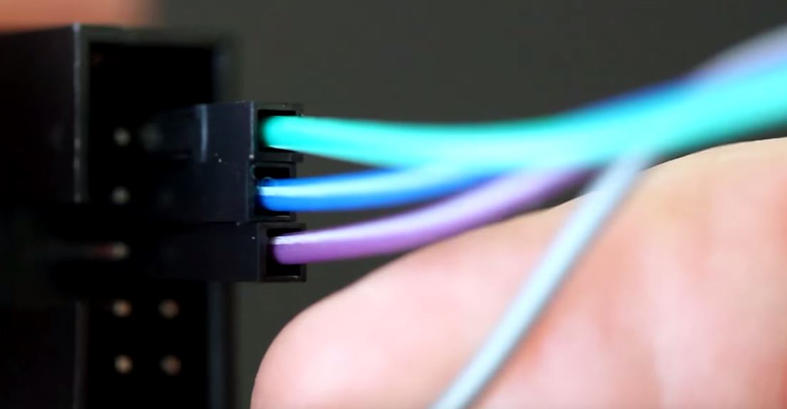
The final pin is 3.3v, the power supply, and we’ll use the last pin,
the gray one.
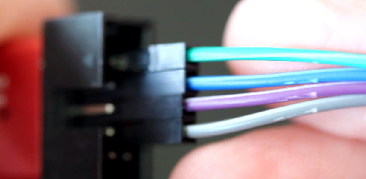
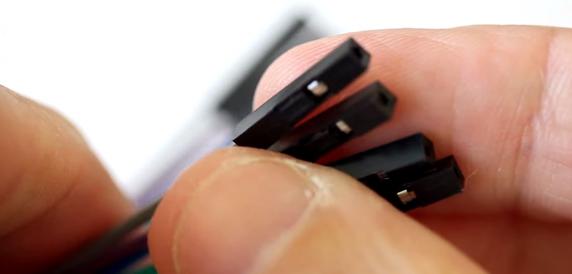
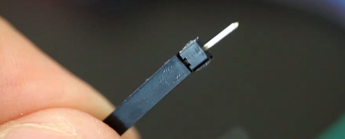
Now we have all of our headers inserted into our pins connected. We can put the other side on
the appropriate pins on the breadboard, but first we need to make these pins male so we can plug
them into the breadboard. I’m going to use a header strip, and break off one for each female
header.
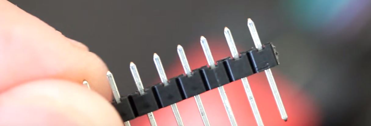
I need to prepare this so I’ll have enough metal to go into the breadboard and go into
the female header snugly, so I’m simply going to bring it between these pliers and bring it
down even. When all four are done, each one can be inserted into the female header.
They are now snug so they should stay in without a problem. Now we need to find out where to plug these
into the breadboard.
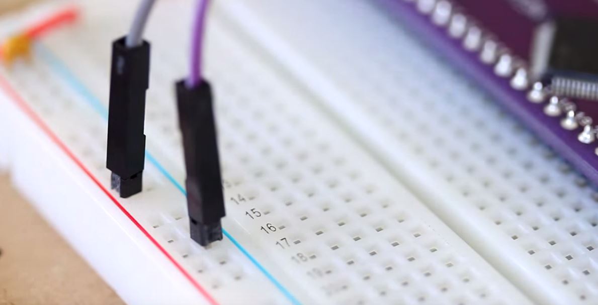
The only pins we really need to find are for the SWCLK and the SWDIO. Let’s take a look and see
where we can find them. The SWCLK is at pin 49 and the SWDIO is at pin 46. We don’t really need
to be concerned with the ground and 3.3v because we’re just going to put those in the power rails
anyway, so the 3.3v pin will go to the plus rail and the ground will go to the minus rail. The
SWCLK which is my green wire is connected to pin 49 and the SWDIO which is my blue wire is on pin
46.
The pulling high and pulling low of these two pins (mentioned in the next paragraph) may not be
necessary. Only use this technique if you have problems uploading code to the microcontroller.
This condition is actually resolved internally within the microcontroller.
Because the SWDIO and SWCLK are floating pins, they need to be externally pulled high or pulled
low. For the SWCLK, that pin needs to be pulled low. First I’m going to put a resistor on each
pin. What I’m doing is taking this tie strip from the pin on the breakout board and I’m jumping
to the next tie strip using a resistor. Since these tie strips aren’t connected, I can put a
resistor across those and now I have a resistance between this tie strip and this tie strip.
Now all we have to do is connect these tie strips to the appropriate power rail to bring this
one low and this one high. We’ll start with the SWCLK and we’ll bring that low. We’ll place it
on the tie strip and then the next pin will go to the negative rail. Now for the SWDIO, we’ll
place that first on the positive and then on the tie strip for SWDIO. The SWCLK has a resistor
and is being connected to the low, and the SWDIO has a resistor and is connected to the high
which is 3.3v.
Now we’ll take the remaining wires which are the ground and 3.3v. The ground
was the purple one and the 3.3v was the gray one. We’ll connect those to the power rail. We’ll
take the ground (purple) and place it on the negative rail, and the 3.3v (gray) and place it
on the positive rail.
We’ve connected everything we need to be able to communicate to the microcontroller and send
programs to it, but we haven’t added anything to the board that will communicate to us that the
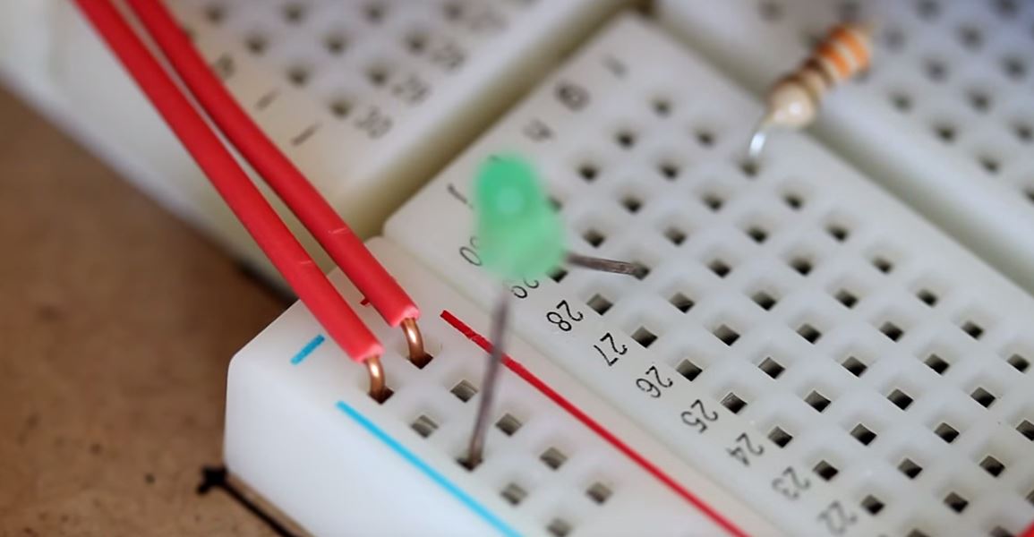
program is working. We’re going to add an LED to
one of the pins and we’ll turn the LED on and
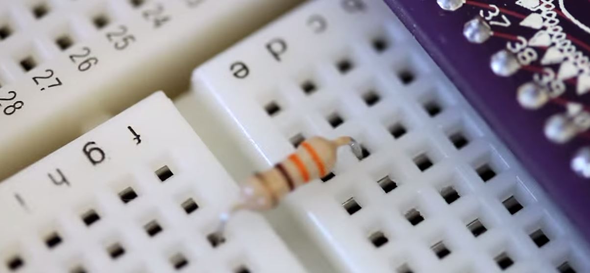
off by controlling that particular pin. For the simple function of turning on and off an LED,
I’m going to select pin PC6 which is connected to pin 37 on the breakout board. Since LEDs need
resistors I’m going to add a 330 ohm resistor
across the two tie strips that is connected to pin 37.
The LED will be connected from that tie strip to the ground because when the pin is powered it
will be on the positive side of the LED and then the negative side of the LED will be on ground.
The ground side of the LED will be the side of the LED that has the flat.
The flat side of the
ground side is the cathode, and the other side which is the positive side is the anode. This
completes the circuit building for the first project, connecting the ST-Link interface to the
microcontroller and connecting some device to be able to view our program working.
ARM STM32 Microcontroller Series Index:
Introduction
Installing and Setting up the IDE
Connect the ST-Link v2 Interface to your Computer
Introduction to the CoIDE
Connecting the ST-Link v2 to the STM32 Microcontroller